In the electrical world, a handful of principles are so foundational that everything else seems to hang from them.
Kirchhoff’s Voltage Law, KVL, is one of those bedrock rules. Whether you’re wiring a kitchen ring circuit in Leeds or troubleshooting a three-phase motor control in Aberdeen, you’re using it, consciously or not.
KVL is not some abstract idea locked away in textbooks. It’s the invisible checklist behind how voltages behave in a circuit. Ignore it, and your design or fault diagnosis starts leaning on guesswork.
In the UK, with our mix of old installations and cutting-edge renewable systems, this law plays a part everywhere, in BS 7671 design calculations, in renewable battery banks, even in the small control loops buried inside HVAC panels.
The Origins And Context Of Kirchhoff’s Laws
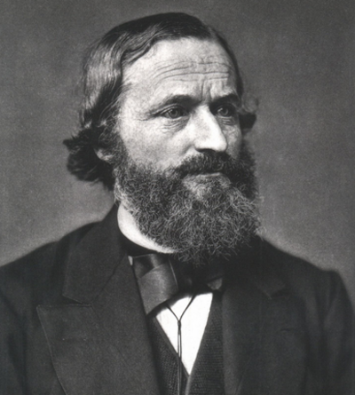
Gustav Kirchhoff, a German physicist, set out his circuit laws in the 1840s. It was a time when telegraph systems were still a novelty, and electrical theory was trying to find its feet.
Before Kirchhoff, engineers understood Ohm’s Law, the link between voltage, current, and resistance, but complex circuits with multiple loops or sources were tricky.
Kirchhoff’s contribution was to take the principle of energy conservation and apply it directly to circuits.
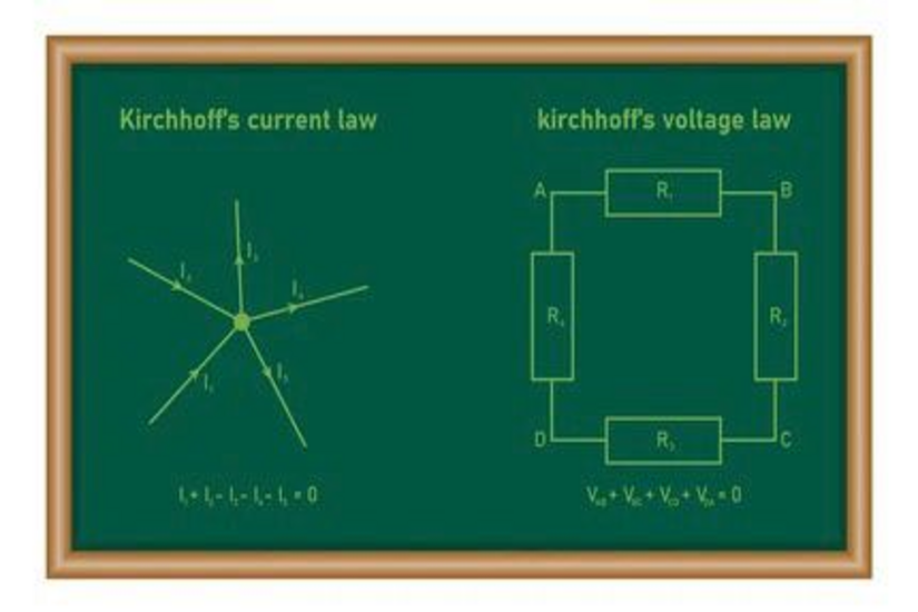
He gave us two rules: one for currents (Kirchhoff’s Current Law) and one for voltages (Kirchhoff’s Voltage Law). Together, they became the analytical toolkit for breaking down even the messiest of wiring diagrams.
The voltage law, in particular, follows from a simple physical truth: energy doesn’t appear or vanish as it moves around a closed loop.
Whatever the sources supply must be exactly balanced by the energy drops in the components.
In the UK today, this underpins how electricians verify design calculations, check for voltage drop compliance, and analyse faults in both DC and AC systems.
Kirchhoff’s Voltage Law: Definition And Core Principle
Kirchhoff’s Voltage Law states:
The algebraic sum of all voltages around any closed loop in a circuit is zero.
It’s a formal way of saying: if you start at one point in a circuit, walk around the loop adding up the voltage rises and drops, you’ll end up back at zero when you return to the starting point.
Why? Because electrical energy is conserved. The supply gives energy to the charges; components like resistors, motors, and lamps take it away as heat, light, or work. By the time you’re back to the starting point, there’s no “leftover” voltage.
Mathematically, it looks like this:
ΣV = 0
Where voltages across each component are given a sign depending on whether you move from negative to positive (rise) or positive to negative (drop) during your loop.
An everyday analogy? Think of walking a circular hiking trail with climbs and descents. Add the gains and losses in elevation, you’ll end up with zero net change once you’re back where you began.
In UK electrical work, this principle applies to everything from a single resistive load to a complex building services control panel. It’s how you make sure what’s supplied by the source is exactly accounted for in the loads.
Understanding “Closed Loops” In Circuits
A closed loop is simply a path through a circuit that starts and ends at the same point, without lifting your “pencil” from the diagram.
In a basic series circuit, say, a battery, a lamp, and a switch, the loop is obvious. Current leaves the battery, passes through the lamp and switch, and returns.
In more complex setups, you might have several loops. Multi-loop or mesh circuits are common in industrial control gear and in certain lighting control systems. Each loop is a candidate for applying KVL.
UK examples:
- A lighting ring circuit in a commercial building, where multiple fittings and junctions form several potential loops.
- A motor control circuit with overloads, contactors, and auxiliary relays, all linked in a control loop.
When applying KVL, it’s important to define your loop clearly. You can’t mix and match paths halfway through the calculation.
The law applies only when you complete a full return to your starting point without branching off.
Good schematic reading is half the battle. On UK site drawings, loops are sometimes less obvious than in a classroom example, especially if the diagram is a modification of older plans. Spotting the loop correctly ensures KVL gives you meaningful results.
How KVL Works In DC Circuits?
In direct current (DC) circuits, voltages are constant in time, which makes KVL applications fairly straightforward.
Here’s the step-by-step process:
- Choose a loop in the circuit diagram.
- Assign a direction to travel clockwise or anticlockwise, and stick with it.
- Mark polarities on each component in line with the chosen direction.
- Add rises and drops algebraically, voltage rises get a “+”, drops get a “–” (or vice versa, as long as you’re consistent).
- Set the sum equal to zero and solve for the unknowns.
Example: A 12 V battery supplies two resistors in series, 4 Ω and 8 Ω. Travelling from the negative battery terminal: +12 V (rise), –I×4 Ω (drop), –I×8 Ω (drop) = 0.
That gives 12 – 4I – 8I = 0 → I = 1 A.
Common mistakes in UK training assessments include:
- Mixing polarity halfway through the loop.
- Forgetting to include the voltage drop across source's internal resistance.
- Confusing this with current division rules (that’s KCL territory).
In real UK installations, you might apply this to calculate voltage drops in a long DC cable run for a PV array.
You’d sum the supply voltage and subtract each cable and load drop to see if the end voltage meets the design spec.
How KVL Works In AC Circuits?
Alternating current (AC) brings in an extra twist: voltages can be out of phase with each other. That’s why KVL in AC often involves phasors and complex numbers.
Instead of simple resistances, you’ll have impedances (Z) that combine resistance, inductive reactance, and capacitive reactance.
The law still applies, the sum of voltage rises and drops in a closed loop is zero, but those voltages are now vectors, not just numbers.
Example: A 230 V supply feeding a coil (inductive load) and a resistor in series. The resistor drop is in phase with current; the inductor drop lags by 90°. Using phasor addition, you sum them vectorially to match the supply.
For UK electricians, this matters in:
- Motor circuits where inductive reactance plays a big role.
- Lighting with large inductive ballasts.
- Long cable runs where capacitance can’t be ignored.
The principle is the same: choose a loop, assign directions, and sum all voltages (phasor form) to zero.
Even in AC, sign conventions matter. Mixing them can throw your results off completely, a common issue when moving from purely resistive DC thinking to reactive AC analysis.
KVL And Energy Conservation
KVL isn’t magic. It’s simply the conservation of energy in action.
In any closed loop, the total energy supplied by sources must equal the total energy absorbed by loads. The voltages are just a way of accounting for that energy transfer.
If a 24 V DC supply is feeding a circuit, the sum of voltage drops across resistors, LEDs, and any internal resistance in the source will total 24 V. Energy in equals energy out, no losses unaccounted for.
There are exceptions, or rather, limitations. In circuits with strong time-varying magnetic fields, like in transformers or when conductors loop around inductors, induced voltages can complicate things.
Strictly speaking, KVL holds for lumped element circuits, where the physical size of the loop is small enough that electromagnetic effects don’t dominate.
For most UK electrical work, domestic, commercial, and most industrial, those conditions are met, and KVL applies cleanly.
Practical Applications For UK Electricians
KVL isn’t just theory, it’s a working tool on site.
Fault-finding – Say you’re tracing a voltage drop problem on a lighting circuit. By applying KVL around the loop, you can confirm whether the drop is all in one segment (loose termination, damaged cable) or distributed across multiple runs.
Design verification – BS 7671 sets limits on allowable voltage drop from origin to point of use. KVL is the underlying logic: supply voltage minus all load and cable drops must still meet the equipment’s operating needs.
Battery banks – In renewable systems, you can check the total voltage across a series bank matches the sum of individual batteries. If not, KVL tells you there’s a weak or failing cell somewhere.
Control circuits – In building services, loops controlling HVAC dampers, pumps, or fans often have multiple relays and sensors. KVL helps verify that the supply and component drops match up, ruling out hidden wiring faults.
Applied with a multimeter and a schematic, KVL can be as practical as any hand tool in the van.
Common Pitfalls And Misunderstandings
A few traps catch people out time and again:
- Forgetting all drops – Every component in the loop has a voltage drop, including the source’s internal resistance.
- Mixing up laws – KVL is about voltages in loops; KCL is about currents at junctions. They’re linked but not interchangeable.
- Polarity errors – Changing direction mid-loop without adjusting signs leads to nonsense results.
- Ignoring real-world effects – Heat, corrosion, and loose terminations change resistance values, so measured drops may not match textbook calculations.
In UK site work, sloppy sign convention is the biggest culprit. Consistency is key; pick a loop direction and stick to it from the first terminal to the last.
KVL In Complex Networks And Mesh Analysis
In multi-loop circuits, KVL teams up with mesh analysis. Each independent loop gets its own KVL equation, and solving them together gives the unknown currents or voltages.
Example: Two loops share a resistor. Each loop’s KVL equation includes that resistor’s drop, but with opposite signs depending on current direction.
For electrical design engineers, mesh analysis using KVL is standard practice in:
- Control panel design.
- Multi-supply emergency lighting systems.
- Complex industrial motor control boards.
The maths can look intimidating at first, but it’s simply more of the same KVL logic, just applied to multiple loops at once.
It’s worth noting that software packages like AutoCAD Electrical or UK-specific design tools still rely on KVL under the hood. The calculations may be hidden, but the principle hasn’t changed since Kirchhoff’s day.
Tools And Techniques For Applying KVL In The Field
You don’t need exotic kit to use KVL on site.
- Digital multimeter – For measuring voltage drops and source voltages.
- Clamp meters with voltage probes – Useful when you can’t break the circuit.
- Accurate schematics – Paper or digital, without them, you’re working blind.
- Circuit simulation software – Even free or UK-accessible online simulators let you rehearse KVL on a virtual circuit before touching the real one.
A well-marked drawing with loops highlighted speeds up real-world troubleshooting enormously.
Standards, Education, And Industry Practice In The UK
KVL is embedded in UK electrical education. City & Guilds 2365, 2391, and equivalent qualifications all teach it early on.
In practice, it supports compliance with BS 7671 voltage drop limits, helps ensure energy efficiency, and backs up the diagnostic process during EICR inspections.
Bodies like NICEIC and the ECA incorporate it into their training, not as abstract maths but as a practical, on-the-job skill.
Bottom Line
Kirchhoff’s Voltage Law is as relevant in 2025 as it was in the 19th century. It’s not just a classroom concept, it’s a working tool for UK electricians, engineers, and designers.
Whether you’re verifying a design, hunting down a fault, or learning the ropes, KVL is part of the craft.
For those wanting a risk-free way to practise circuit analysis before going hands-on, Tradefox offers simulation tools ideal for tradespeople, electricians, and plumbers, all without the danger of live work.
Understand it well, and you’ll see it everywhere in every switchboard, every cable run, every control loop. KVL isn’t just theory; it’s how electricity behaves, day in, day out.